
After looking at the DMG schematics, i got the idea to bypass the whole audio path of the gameboy and recreate my own output to see if we can get a better sound.
The idea behind this is to get better "pro-sound" output whit more BASS, because the DMG 1uF coupling caps will kill all deep bass.
I saw somewhere that a trick was to short the 1uF caps, but was a quite strange way of doing this because you will get the DC offset directly in the phone amp.
So my way of doing a prosound is connect directly at the CPU output (easier to solder directly before the 1uf caps) and add another circuit for DC coupling and High Z output leaving the original circuitry for headphone and speaker intact.
Schematics will come soon ..
Results : As expected, we get a much better bass response, for bass i mean sub bass(20-50Hz)
Some audio examples from LSDJ with associated the frequency analysis
I've tested with the same "song" each time with the classic prosound (pre-pot) and with my new pro-sound version using different caps value.
Prosound output directly connectin to my Mac internal input and saved without any compression (PCM 16bit ). No sound post processing.
Sorry for the "song" but is only a Bass test, not a full track as i don't know LSDJ that much
Sound example Original Prosound
Using Pre-Pot Classic Prosound on DMG-01
Original Prosound Spectrum analysis :
 Peak 36 Hz = -21.2dB
Sound example noizeInaBox Prosound using 2u2 Cap
noizeInaBox Prosound 2u2 Cap
Prosound using 2u2 Spectrum analysis :
 Peak 36Hz = -17.9dB ... +3.3dB than orignal prosound .. yeah .. i like sub bass
Sound example noizeInaBox Prosound using 10u Cap :
noizeInaBox Prosound 10u Cap
Prosound using 10u Spectrum analysis :
 Peak 36Hz = -17.6dB ... +3.6dB than orignal prosound .. yeah .. will buy a subwoofer :)
Sound example noizeInaBox Prosound using 100u Cap
noizeInaBox Prosound 100u
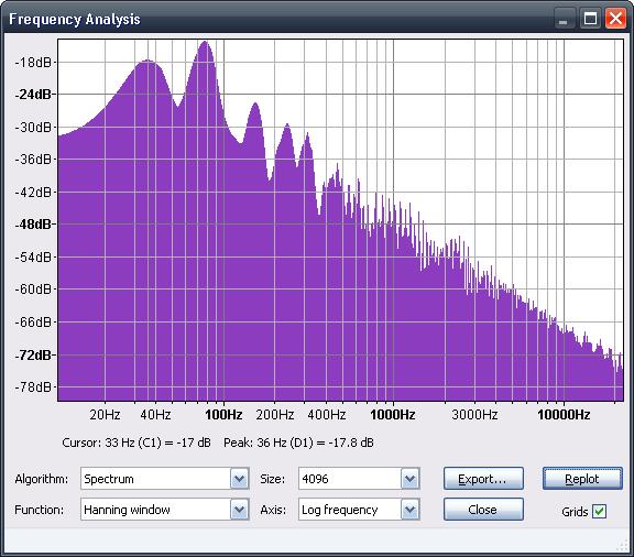
Prosound using 100u Spectrum analysis :
 Peak 36Hz = -17.8dB ... +3.4dB than orignal prosound .. nothing more ..
I know the spectrum analysis look quite identical,but look closer at the lower frequencies (20-50Hz) and remember that 3dB more is like double power.
In order to do some better testing, i needed to use white noise, luckily the Gameboy got a noise channel so i tried the same spectrum analysis using the Gameboy white noise (white noise normally is all frequencies in the same time at same level) :
Original Prosound using white noise Spectrum analysis:
 50Hz = -44dB ... look at 20Hz ..
noizeInaBox Prosound 10u cap using white noise Spectrum analysis:
 50 Hz = -41dB +3dB than orignal prosound and re look at 20 Hz..
noizeInaBox Prosound 100u cap using white noise Spectrum analysis:
 50 Hz = -41dB +3.dB than orignal prosound
My Conclusion :
Will build my nexts prosounds using my circuit because i like deep bass. i think the selected cap value will be 10u because you don't gain anything more with a bigger cap.
Another remark.if there is some low freq. noise, they will not be filtered with this prosound.
This method need more testing because it is only the first tests, but look good .
Didn't tested yet if this affect in any way the headphone or speaker output.
And remember that is is only for "enhance" sub bass
As it need more components, i will do a SMT PCB with some Oxicaps.
If it works fine, you will see soon on the market the noizeinabox prosound pcbmount
The idea behind this is to get better "pro-sound" output whit more BASS, because the DMG 1uF coupling caps will kill all deep bass.
I saw somewhere that a trick was to short the 1uF caps, but was a quite strange way of doing this because you will get the DC offset directly in the phone amp.
So my way of doing a prosound is connect directly at the CPU output (easier to solder directly before the 1uf caps) and add another circuit for DC coupling and High Z output leaving the original circuitry for headphone and speaker intact.
Schematics will come soon ..
Results : As expected, we get a much better bass response, for bass i mean sub bass(20-50Hz)
Some audio examples from LSDJ with associated the frequency analysis
I've tested with the same "song" each time with the classic prosound (pre-pot) and with my new pro-sound version using different caps value.
Prosound output directly connectin to my Mac internal input and saved without any compression (PCM 16bit ). No sound post processing.
Sorry for the "song" but is only a Bass test, not a full track as i don't know LSDJ that much
Sound example Original Prosound
Using Pre-Pot Classic Prosound on DMG-01
Original Prosound Spectrum analysis :

Sound example noizeInaBox Prosound using 2u2 Cap
noizeInaBox Prosound 2u2 Cap
Prosound using 2u2 Spectrum analysis :

Sound example noizeInaBox Prosound using 10u Cap :
noizeInaBox Prosound 10u Cap
Prosound using 10u Spectrum analysis :

Sound example noizeInaBox Prosound using 100u Cap
noizeInaBox Prosound 100u
Prosound using 100u Spectrum analysis :
I know the spectrum analysis look quite identical,but look closer at the lower frequencies (20-50Hz) and remember that 3dB more is like double power.
In order to do some better testing, i needed to use white noise, luckily the Gameboy got a noise channel so i tried the same spectrum analysis using the Gameboy white noise (white noise normally is all frequencies in the same time at same level) :
Original Prosound using white noise Spectrum analysis:

noizeInaBox Prosound 10u cap using white noise Spectrum analysis:

noizeInaBox Prosound 100u cap using white noise Spectrum analysis:

My Conclusion :
Will build my nexts prosounds using my circuit because i like deep bass. i think the selected cap value will be 10u because you don't gain anything more with a bigger cap.
Another remark.if there is some low freq. noise, they will not be filtered with this prosound.
This method need more testing because it is only the first tests, but look good .
Didn't tested yet if this affect in any way the headphone or speaker output.
And remember that is is only for "enhance" sub bass
As it need more components, i will do a SMT PCB with some Oxicaps.
If it works fine, you will see soon on the market the noizeinabox prosound pcbmount


