jeudi 6 décembre 2012

TeensyBoy

What is a TeensyBoy ?

EDIT :Due to some people request, the teensyboy source has been released on googlecode page
if you want to test/edit/enhance this project please download the source and let's rock.

TeensyBoy is just a ArduinoBoy code port for a Teensy uC.
What is ArduinoBoy? ArduinoBoy is a device using a Arduino (developped by Trash80) that enable MIDI capabilities for a old Nintendo GameBoy using special software like LSDJ, nanoloop, mGB.

Why porting ArduinoBoy on a Teensy ?
There is several reason but the most important one is that teensy is capable to emulate a Midi compliant device using midi, so TeensyBoy is using USB Midi instead of classic midi. So plug it in your USB port and it is automaticaly detected as a midi device.
The other reason are the price of a teensy is lower than a Arduino, it is much smaller, TeensyBoy will need less components that a ArduinoBoy (not optocoupler for example), using USBMidi library, code is less complicated, etc...
The code for Teensy is based on the Original ArduinoBoy created by Trash80, most of the code don't have changed.


The code is finished but still need tests and tweaking :

  • LSDJ slave mode : finshed and working
  • LSDJ Master mode : finshed and working
  • LSDJ keyboard mode : finished and working
  • Nanoloop mode : finished but cannot test it (don't own nanoloop)
  • mGB mode : finished and sems working need further tests.
  • LSDJ map mode : not tested yet
  • LSDJ  Midiout : not tested yet
All tests done are just the functionality working or not, i don't ow n a ArduinoBoy so i can't compare both.
I don't know if it less responsive or if some thing is not working as expected, if someone want to do tests or compare with the ArduinoBoy please feel free to contact me.

Note : all sysex stuff has been removed because it need much more time to port it, and not sure if it is a lot used by chipmusicians. (sysex stuff seems to add config via maxmsp patch)

TeensyBoy schematics :


Teensy Cabling diagram :


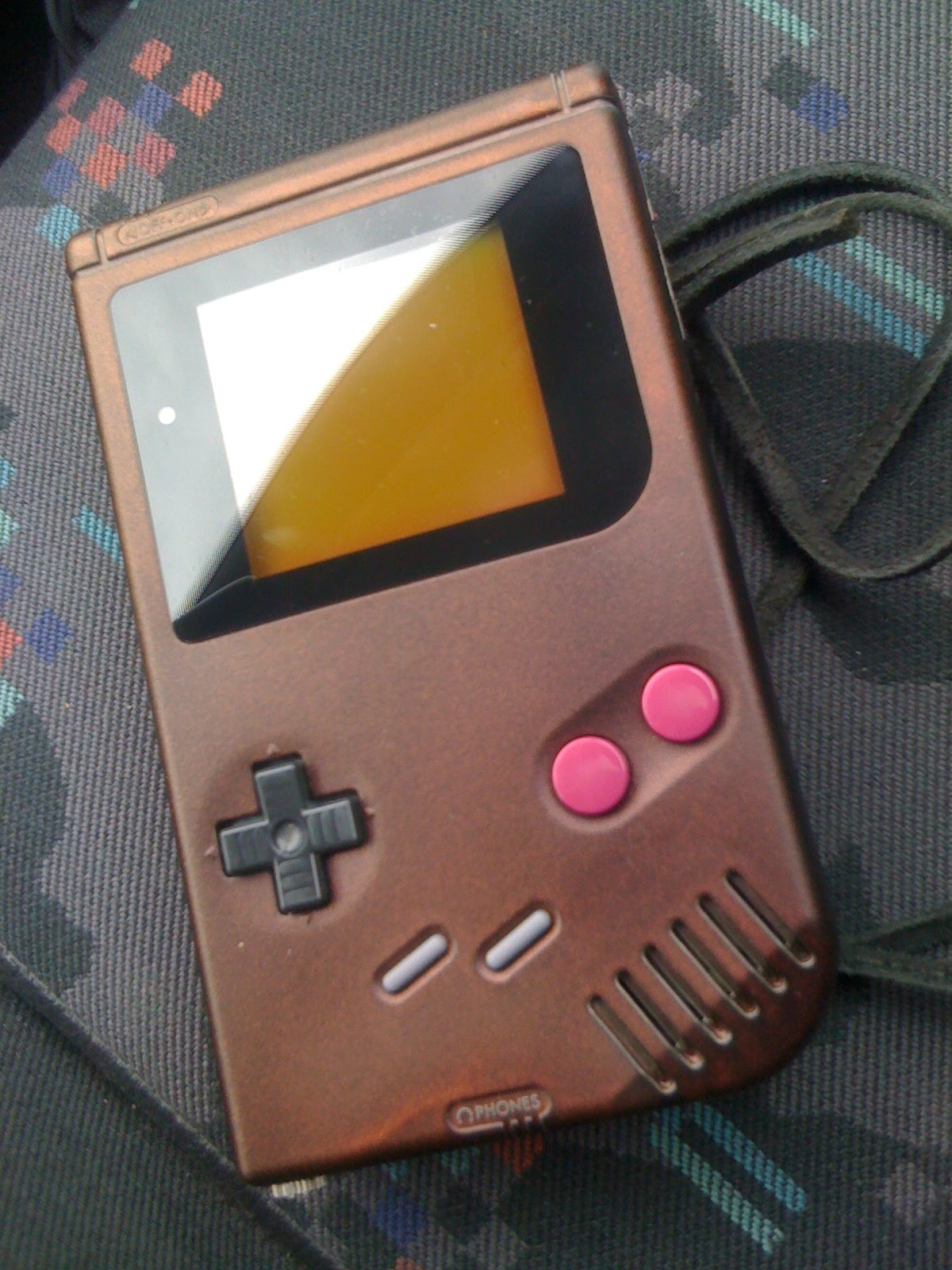
Blurry Picture of the testing device :


Code will be available on my googlecode page once all mode been tested and working.


mardi 10 juillet 2012

noizeInaBox temporary "shop" is available

I will finally create a small online shop for few devices i've created.
So currently there is no official online shop but i created a page with the things i sell.
You can find the shop page in the "tab" between Acceuil and Bookmark ..

lundi 9 juillet 2012

noizeInaBox DMG deep bass PCB mount

Currently working on my Deep Bass DMG PCB mount.
It will be a full headphone PCB replacement with 2 new 3.5 mm audio jack. so you won't need to desolder the original DMG headphone jack.
For sound output it will use high quality OxiCaps.

It is impossible to find a 3.5mm jack with the same size and feature as the original gameboy one. (independent normally connected switch), i found a suitable one but with a normally open switch. so i needed to add a 5V cable to it to be able to do the Headphone/speaker switch.

As the prosound jack is the same i've a normally open switch left, which i don't know how to use it for.
i was thinking of some start/select illumination when you plug the prosound jack in.
globally it is a switch that close when you plug the prosound jack in. so it can be used for anything.
if you have a good idea, please let me know.


vendredi 6 juillet 2012

noizeInaBox Selectable GB Clock working fine.

I soldered and tested the noizeInaBox Selectable GB Clock and it's working perfectly.


By connecting  VCC or GND to the A and B pins, you can select the desired frequency .


Some pictures and Scope screenshots

 compare the size with a GB battery.
if you look carfeully you can see a short between 2 pins of the IC, this is normal, i forgot a trace on the PCB during PCB creation .. huuuu ..
There is also 3 pad on the board, it is to set a default "value" the the pin B. For example make a short between pad B and GND then add a SPDT swith on GND, VCC and Pin A, will make a 4Mhz/2Mhz selectable oscillator for your GB (if you don't want lower selectable freq).


Some scope trace:
You can see that the frquency is not correct, because there is some drift in the freq. due to the way a tested it, the circuit was plugged on a breadboard then from breadboard to the GB.
also, the GB was powered by a very crappy switching power supply.


The original  GB crystal.


If someone is interested i've a few to sell, with component already soldered. just drop me a email.

jeudi 5 juillet 2012

my selectable GB clock PCB just arrived

I've build a precision selectable Gameboy clock module which got 4 selectable frequency.
1: 4.194304MHz
2: 2.097152MHz
3: 1.048576MHz
4: 524.288kHz

The board is very small 13 mm , and by adding 2 switchs, you can select theses frequencies.
It's time for some SMD soldering.
Some pics :

sorry for the crappy pictures.


mercredi 13 juin 2012

DMG Deep Bass Prosound à la noizeInaBox

After looking at the DMG schematics, i got the idea to bypass the whole audio path of the gameboy and recreate my own output to see if we can get a better sound.

The idea behind this is to get better "pro-sound" output whit more BASS, because the DMG 1uF coupling caps will kill all deep bass.

I saw somewhere that a trick was to short the 1uF caps, but was a quite strange way of doing this because you will get the DC offset directly in the phone amp.

So my way of doing a prosound is connect directly at the CPU output (easier to solder directly before the 1uf caps) and add another circuit for DC coupling and High Z output leaving the original circuitry for headphone and speaker intact.

Schematics will come soon ..

Results : As expected, we get a much better bass response, for bass i mean sub bass(20-50Hz)

Some audio examples from LSDJ with associated the frequency analysis
I've tested with the same "song" each time with the classic prosound (pre-pot) and with my new pro-sound version using different caps value.
Prosound output directly connectin to my Mac internal input and saved without any compression (PCM 16bit ). No sound post processing.
 Sorry for the "song" but  is only a Bass test, not a full track as i don't know LSDJ that  much

Sound example Original Prosound

Using Pre-Pot Classic Prosound on DMG-01
Original Prosound Spectrum analysis : 

                                        Peak 36 Hz = -21.2dB


Sound example noizeInaBox Prosound using 2u2 Cap
noizeInaBox Prosound 2u2 Cap
Prosound using 2u2 Spectrum analysis :

                Peak 36Hz = -17.9dB ...  +3.3dB  than orignal prosound  .. yeah .. i like sub bass


Sound example noizeInaBox Prosound using 10u Cap :
noizeInaBox Prosound 10u Cap
Prosound using 10u Spectrum analysis :

 Peak 36Hz = -17.6dB ...  +3.6dB  than orignal prosound  .. yeah .. will buy a subwoofer :)


Sound example noizeInaBox Prosound using 100u Cap
noizeInaBox Prosound 100u
Prosound using 100u Spectrum analysis :

         Peak 36Hz = -17.8dB ...  +3.4dB than orignal prosound  .. nothing more ..


I know the  spectrum analysis look quite identical,but look closer at the lower frequencies (20-50Hz) and remember that 3dB more is like double power.

In order to do some better testing, i needed to use white noise, luckily the Gameboy got a noise channel so i tried the same spectrum analysis using the Gameboy white noise (white noise normally is all frequencies in the same time at same level) :

Original Prosound using white noise Spectrum analysis:

                                         50Hz = -44dB  ... look at 20Hz ..


noizeInaBox Prosound 10u cap using white noise Spectrum analysis:

                     50 Hz = -41dB  +3dB  than orignal prosound  and re look at 20 Hz..

noizeInaBox Prosound 100u cap using white noise Spectrum analysis:

                                          50 Hz = -41dB   +3.dB  than orignal prosound

My Conclusion :
Will build my nexts prosounds using my circuit because i like deep bass. i think the selected cap value will be 10u because you don't gain anything more with a bigger cap.
Another remark.if there is some low freq. noise, they will not be filtered with this prosound.
This method need  more testing because it is only the first tests, but look good .
Didn't tested yet if this affect in any way the headphone or speaker output.
And remember that is is only for "enhance" sub bass 

As it need more components, i will do a SMT PCB with some Oxicaps.
If it works fine, you will see soon on the market the noizeinabox prosound pcbmount 


mercredi 6 juin 2012

Finished DMG-01

I just finished my Game boy DMG-01


It doensn't have much funky mod, only the classic
  • Promod sound mod
  • Green 3 Led backlight
  • Black screen protector
  • custom painting
  • Super Gameboy CPU


vendredi 1 juin 2012

Game Boy Super Game boy CPU Transplant tutorial


I just finished my CPU transplant between my DMG-01 and a Super Gameboy cartridge.

For Info :With this mod you wont' get more cpu power, or anything similar, it will only change the boot delay, so each time you power-up  the GB, it will boot very fast into the game and you won't get the Nintendo boot sound.

Don't try this if you don't have good soldering skills.

I decided to make a little tutorial, well 2 tutorial in fact. so here is the fast tutorial
1. Desolder your Super Gameboy CPU
2. Desolder your Gameboy CPU (DMG-01)
3 Solder you SGB cpu in place of the GameBoy cpu
That's it.

As I've done some picture of the process, so I did a longer tutorial with pictures.

Super Game BOY CPU transplant Tutorial 

So you want to transplant your super gameboy cpu in your gameboy ? 

Warning: if it’s the first time you desolder or solder SMT components, don't try on your SGB and GB use a old motherboard you don’t need anymore or similar to train you a bit..

This mod need good soldering skills. (normally if you have the skill to do this, you should not need any tutorial )

Tools needed  :
  • Gameboy DMG-01
  • Super Gameboy cartridge.
  • Gameboy game or lsdj (to test afterward)
  • The special tools to open SGB and Gameboy
  • Solder iron with fine tip (and some solder)
  • Flux
  • Ideally a rework station or some chipquick (everything that you want to remove smt component)
  • Time and patience.

Step 1
Before doing everything check if GB and SGB are working fine.
Open your game boy and your super gameboy to make them ready for the transplant.


Step 2 
Desolder the Super gameboy CPU using the rework station or with your preferred method.
(I will not explain how to do it because there is several tutorials on how to desolder SMT component on internet. Just use Google)
 Try to not over heating the CPU during the desoldering process.
Clean the pins of your desoldered SGB cpu with the solder iron


Step 3
Desolder the gameboy CPU using the rework station or with your preferred method.
Do not heat to much the board, CPU or other component. You can lift up a little bit the capacitors near the GB CPU to be sure you don’t touch them with your rework station.
Once removed, check to board to see if everything looks ok. 


Step 4
Clean PCB pads after desoldering.
You can use solder wick  to clean or you can put flux on the pads and using the solder iron go across each pad QUICKLY to  melt the solder and clean the pads ,after that clean the flux.

If you use solder wick method, it may be easier to put in place the SGB chip after because all solder will be removed and pads are flat but I don’t like this method because it heat a lot more the PCB than using the solder iron and flux.
Do not apply too much heat because the pads could lift up and it will be very difficult to repair (or impossible).


Step 5
 Place the super Game boy CPU precisely to match the pads (check the orientation notch)
Put a little bit of solder on your iron tip.
Hold it in place and using the iron with fine tip, solder one CPU pin in the corner.
Recheck the chip placement and if it’s fine solder one opposite CPU pin
It is easier if you add some flux on the pin you want to solder before soldering.
 After that your CPU should not move anymore


Step 6 
Put more flux on all pins.
Solder all remaining CPU pins, there are several technique to solder them, check video on internet on  how to solder SMT chip. (solder each pin individually or with a little bit of solder on the iron tip move across the pads)
If you make a join between 2 pins, don’t worry you can remove them using some solder wick


Step 7
Inspect attentively all your work, especially  joins between pins or if a pin is not correctly soldered (a magnifier would help). this is a crucial step.


Step 8
Clean the Flux.

Don’t forget this step because depending the flux you use, it can be conductive, and if it’s the case your Game boy will not work or could even destroy your GB.

It happen to me, I didn’t clean the flux  (sparkfun Flux #2331-zx) and the GB didn’t want to boot. After cleaning the flux everything was working fine

If you lifted up the capacitor near the CPU, it is a good time to put them in place again.(before mounting the board in the case)
Solder job is done. :) 


Step 9
Test your Gameboy and enjoy the fast boot (don’t forget to put a game or LSDJ)

If it doesn’t work (nothing appear on the screen and contrast not working) double check your CPU orientation and all soldered pins . (try to resolder all pins and check solder joins)


That's it ... job finished.


Quick video to see the Super Game boy fast boot. :


(sorry for the high compression of the video due to upload on blogger, we don't see anymore the marking on the chips) .

Disclaimer: I am not liable for any damage caused to you, your GameBoy or Super Game Boy due to human error.

Special Thanks to NeX for the idea and the help.


vendredi 25 mai 2012

GameBoy screen LCD fix with rework station (hot air)

So i tested my 2 DMGs and guess what .. lcd probs .. vertical lines problems.
-  on one Gb i got one line not working.
-  on the other a lot of line are not working maybe 15 lines on each side of the screen.
After some google search it seems that it is quite easy to fix. i saw that with a solder iron we can fix that.
As i have a rework station (hot air) i decided to try with my rework station instead of the solder iron.
I tested to fix the most problematic screen first .. and the result are .....taadaa... work like a charm, using rework station to fix this it's like magic.

I would just do a little warning : do not put too much air flow and the most important DO NOT PUT TOO MUCH HEAT. I would say do not exceed 150 C (degrees celsius)

If you set your rework station above 150C it can melt the plastic of the LCD ..

Some pictures:

                        If you look correctly you can see that i've started to melt the bottom of the screen (yes i started this job at approx 200 C)
The white thing on the bottom of the screen  is the electrical table to fix the black rubber (the one you need to remove to fix that)

and taaddaa .. it work fine again .
Sorry i didn't take any picture before the fix, and during the fix, will try to take some for the next one.


Quick picture for the next step, remove this baby and replace it with the super gameboy one.

I just got a good deal on few super game boy, if it is easy to replace i could do some mod service for game boys.


Just got 2 Gameboy (DMG-01)

Just got 2 DMG-01 for a few CHF .. good deal.
I know a few friends who  like and do some chipmusic, so why not add some mod to the gameboy and give it for testing to chipmusic friends.

Mod planned :
- Backlight
- Pro sound
- Super gameboy CPU transplant (great for live act. ultra fast boot and no kling)
- maybe integrate a midi input inside the gameboy
- idea for a distortion inside ..
- some paint job (pimp my DMG)


vendredi 23 mars 2012

Overdrive distortion progress.

Still working on my Overdrive distortion and it is not easy as i was thinking.
Here are the spec i planned for this circuit.

- Soft Clipping (on op amp feedback) and hard clipping (after opamp) selectable
- Hard clipping with Led (to add some blinking stuff)
- not adding too much noize
- true bypass with 4066
- unipolar supply using mc-09 supply
- get a multi purpose distortion PCB (modify diodes, modify gain with trimmers, etc)


You can find a lot of great distortion on the net .. but almost all are guitar distortion, meaning the input signal is not the same, in my case input signal is about 1 to 2 Vpp which i much more that a guitar signal.
This couldn't be a problem but i can't set a high gain on the op amp because the op amp will clip (due to the limited headroom using a 9V single supply) ans the op amp clipping doesn't sounds good.
The good thing about that is the limited gain is also limited noise, but limited gain is limited distortion.
Soft clipping is done by adding diodes (1n4148 for ex.)  in the feedback path of the 1st opamp.

And for the Hard clipping. i planned to use LEDs, so they will blink when distortion happen, but a Typical Vf of a Led is 2V so after the first soft clipping op amp the signal peak is not very high (due to soft clipping) and the Hard clipping effect of the Leds is not very efficient.


You can see here the a soft clippping but peak voltage is 2 volt so the hard clipping after that will not work well..

Adding the Led after for Hard Clipping we get these results  (in RED) :

 as you see, the hard clipping is not very effective. .
So the solution i was thinking is to add a second opamp and do hard clipping after this second op amp.
(also added Led with a higher Vf to stop hard clipping when gain is  low at the second op amp)


 With R4 and R8 will be potentiometers to control the amount of soft and hard clipping ..
see the results here


need to test it in a real situation, because the mc-09 signal is not a perfect sin wave (of course) and adding accent will boost the signal and add clipping on opamp.