mercredi 1 février 2012

Side project : Monome/Arduinome

Here is a side project i have, Buliding a monome (or arduinome).
I got the PCBs, MCU, silicon buttons for some time ago but didn't get the time to build it.
Finally i started to solder this stuff.
It is based on a biboboard, sparkfun buttons. for the "intelligence" board, i've got  some unsped board (for Arduinome) or a clone of the 40h monome.

 I don't know yet which one i will use for the monome/arduinome. will try both.

Here  some picture of the ongoing build. I won't comment that much the building process as many blog or website already have extensive documentation on this.

Diodes, diodes diodes ...


Soldering Diodes .. 

Finally all diodes soldered.

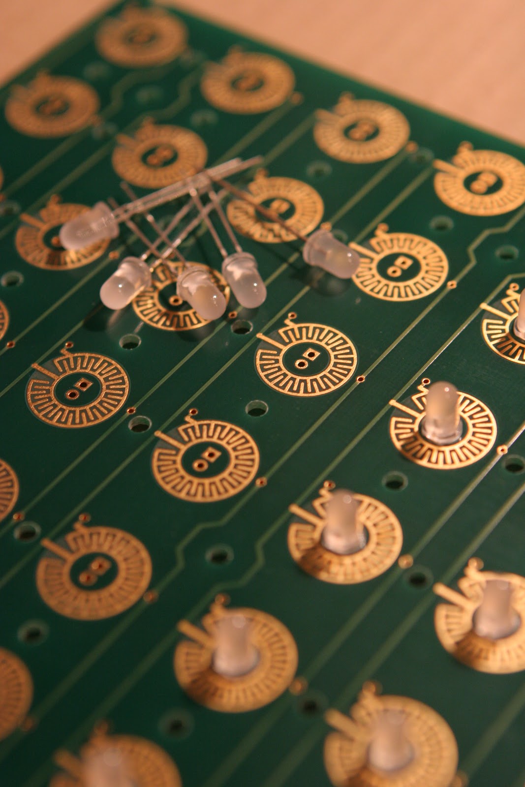
Starting to solders Leds .. 


 More and more leds.


Led Closeup 

Ouf .. finished the led soldering ..


Looks good .. :)

Still no big news ...

No this project is not abandonned ..  and  i know that i didn't put many updates on this blog for a while .. so it's time  for a project status :
I've received the new PCB (only few days ago) but didn't get the time to solder it.

I will also put on this blog some side projects or new toys teardown.
So what's next (i hope this week) :
- Solder and test the new PCB (v0.8)
- Finish and test correctly the Speak Spell Library (basic functions)
- Release the Library code.

A quick picture of the new PCB


If you look at the picture, you can see a Midi in and Out, the Speak Spell won't be able to send midi messages. So midi out is not directly used by the speak and spell., but as the project is open source and driven by a Arduino, you will be able to adapt the code to do send midi messages for anything (add midi nutton, sliders,etc..)
The Speak and Spell Shield is also a Midi shield and all connection between Arduino and Speak and spell bus driver can be removed (with the 10x jumpers) so you can disable all the speak and spell electronics and use it as a pure Arduino midi shield for any projects.


vendredi 30 décembre 2011

New Pcb ordered

The new version of the PCB has been ordered (v 0.8)
There is few schematics changes and the Midi connectors has been moved to the back to be able to put this with the Arduino in a case.


And Schematics :


lundi 19 décembre 2011

updates..

Sorry for the lack of update but was busy theses days.

So i've debugged the PCB and it's working fine now .. (need to manufacture another prototype PCB early JAN.)
For the code i'm trying to convert it to a sort of Arduino library, will be much easier to use.


vendredi 18 novembre 2011

It's christmas day

I just received my PCB prototypes they look nice and good quality. :


So quickly let the iron warm up and start to solder 1st prototype.


I soldered only the important parts, because it is the first prototype and you know the murphy's law.
Let's go for the first tests, add S&S power and test some voltage, Guess what .. IT DOESN'T WORK
I got very strange voltage on the output for the speak and spell bus, it's time to start debugging.

After several tests i found why .. all transistors are inverted ..  but strangely i didn't mounted then wrong, the error comes from Eagle. it seems that Eagle got several the BC558 part and one of this part the collector and emitter is inverted and of course i choose the wrong one ..

Next step, remove the transistors and resolder them in the correct way (what a pain to unsolder them on a double side pcb) and re-test. OK now i got the correct voltages. (-18 or 5V). (not with fresh batteries, problem explained in previous post)

midi optocoupler seems to be working right.
Didn't get time to check other part of the pcb for the moment.

Things to change for the next revision :

- correct silkscreen for transistors
- connect transistor emitters to the regulated 5V supply
- correct the input zener input regulation (put resistor in serie)
- check resistors value to limit the schield current
- remove the -18v / gnd selector jumer (default -18V)
- add a jumper to allow power via arduino.


vendredi 11 novembre 2011

Possible Big design prob found

Argh ...
After reviewing schematics (to adapt them to the teensy) i've found a possible design bug in the schematics.
If my tought are right, i would not be possible to stop the transistor to saturate.


So imagine few values :
Speak and Spell battery + 5V (when Batteries are not new)
Speak and Spell battery : - 12V
Arduino out 1: 5v / 0 : 0V

So when Arduino output =0 , the transistor will saturate and you will 5V on the Speak and Spell BUS
When Arduino output is 5V, the transistor will stop saturate (VBE-0V)and  you will get -12V on the S&S Bus
Everything is fine..

BUT if you put new batteries on the Speak and Spell then the VBATT + is ~ 6.5 V. So  to stop saturate the Transistor we should have min 5.8 V on his base. (VBE 0.7 V).

We have few option to correct this :
- Use darlington transistor (VBE 1.4) 
- Connect Transistor emmiter to regulated 5V supply
- add a diode + a 5V1 zener on emitter of the transistor.

The PCB has been sent to Prod and they are not arrived yet.. and i''ve already spotted a design error.
Why i didn't spotted this during the testing .. ? because i'm using old batteries .. and Speak and spell Battery voltage is 5.3 V. Grr.......


jeudi 3 novembre 2011

Speak and Spell LFO

Still waiting for the S&S interface PCB to arrive from production, i started to build new Speak and Spell features.

I decided to create a PCB of the well known Casper Speak and Spell LFO who add a LFO to the pitch.
See the source at : http://casperelectronics.com/finished-pieces/speak-n-spell/speakspell-bending/
To add some digital feature to this, i was thinking of Digital potentiometer for the LFO controlled via Midi.. but it is another story.

Schematics:

PCB :

3d Preview :