mercredi 1 février 2012

Roland Mc-09 PhraseLab Teardown

As Dave (EEVblog) would say : Don't turn it on, take it apart!

See some picture of a Roland MC-09 inside .. :

The Panel  outside and inside


The main board [Bottom]
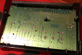
The Main Board [Top]


Detailed Views
          - Power Parts


          -Audio out/in Parts
               Headphone plug
 audio in/out


               -DSP/ uC /RAM /Flash
uController  (only for smartmedia??)
 The DSP
 the Flash
 RAM 1 (maybe for external sample)
 Ram 2
Ram2

   -the DAC (for in and out) the small chip near the RAM

      -   the sliders

   - smartmedia connector

Mainboard with chip placement


Some References, datasheet, chip list of the one i've found (only the identified component)

RAM x1

GM71C18163C
1,048,576 WORDS x 16 BIT
CMOS DYNAMIC RAM

LC324260BJ-60    (4Meg)
Fast Page Mode Dynamic RAM
256K x  16

Flash x1

8M (1M ´ 8/512K ´ 16) BIT
MBM29F800BA-70PFTN

uC x1

16bit microcomputer
H8/3006
Renesas 16-Bit Single-Chip Microcomputer


OP AMP x4
 Dual low-noise operational amplifiers
M5218a
http://bihai.ic37.com/pdf1/pdf1yuikjh78y899/2006-1-1/3591/M5218_www.ic37.com.pdf

AD/DA Converter x1
AK4552
3V 96Khz 24bit
http://www.asahi-kasei.co.jp/akm/en/product/ak4552/ak4552_f01e.pdf

DSP x1
R02231767 RA0A-101 (TC223C080AF-101)
Same as MC-909 or DR-880

Regulator
29M33
UPC29M33A
THREE-TERMINAL LOW DROPOUT VOLTAGE REGULATOR 3.3V

17805T
Standard 78 series, 3-pin regulator


Other Logic ICs

VHC 32
TC74VHC32F
QUAD 2-INPUT OR GATE

VHC74
TC74VHC74F
Dual D-Type Flip-Flop with Preset and Clear

VHC 08
TC74VHC08FT
http://elcodis.com/parts/616126/TC74VHC08FTELM.html#datasheet
Quad 2-Input AND Gate

LV4051A
HD74LV4051A
8-CHANNEL ANALOG MULTIPLEXER/DEMULTIPLEXER


LV245A
SN74LV245A
Octal Bus Transceivers With 3-State Outputs


New toy, Roland PhraseLab Mc-09

I've got a new toy, the Roland PhraseLab Mc-09.
I was not planning to get this, i just fell on this auction on a website like ebay (but only for switzerland) and i got this for less than 100 US dollars. So, i thought why not .. looks funny

Quick description of the device (taken on Roland website) :

The MC-09 PhraseLab is an all-in-one production tool combining a DSP synth, step sequencer, four-part audio looper and effects processor. With this single instrument, musicians can create fat analog synth and rhythm sounds which can be sequenced and then sampled (along with phrases taken from external sources) using the four-part audio looper. An onboard effects processor and cool functions like Chop make the PhraseLab a killer remix machine.
  • - Tabletop synth/audio looper with onboard sequencing and effects
  • - DSP monosynth creates fat synth lead, bass and rhythm sounds
  • - Audio looper plays back 4 monaural phrases up to 6 sec. each
  • - Onboard step sequencer with easy programming including TR-REC method
  • - Easy automatic looping using BPM and measures
  • - Loop Control function for controlling loop playback via step sequencer
  • - 4 built-in effects: Filter, Isolator, Phaser and Slicer
  • - SmartMedia slot for pattern/audio storage; MIDI In/Out


Before getting a lot of people who hate this device put comments on this post i will express my opinion.
- you don't find a lot of these on the net .. so why not getting one..
- i know that the Drum part sound crappy
- the Audio looper (4 samples) compress the sound and is a bit noisy.
- the DSP TB-303 emulator is not the same sound as a real 303, but sounds correct (especially for the price) ..
- Effect are not the most interesting ones
- the Sequencer is okay ..
- it's between a toy and a musical instrument.
- I would not buy this  for the price of a new

Personally  i found it quite funny to play with, it's simple, small, you don't need to use 10 different devices to do some sounds..  and he got some interesting possibilities ..

Finally why putting this "review" of the Mc-09 here on a electronic blog, simply because the one i bought was so dirty that it need a severe cleaning .. and to clean it correctly you need to take it apart.
I found always interesting to see what's inside, and searching the net, there is not that much info on this device .. so why not adding this info myself.


Teardown on the next post


Side project : Monome/Arduinome

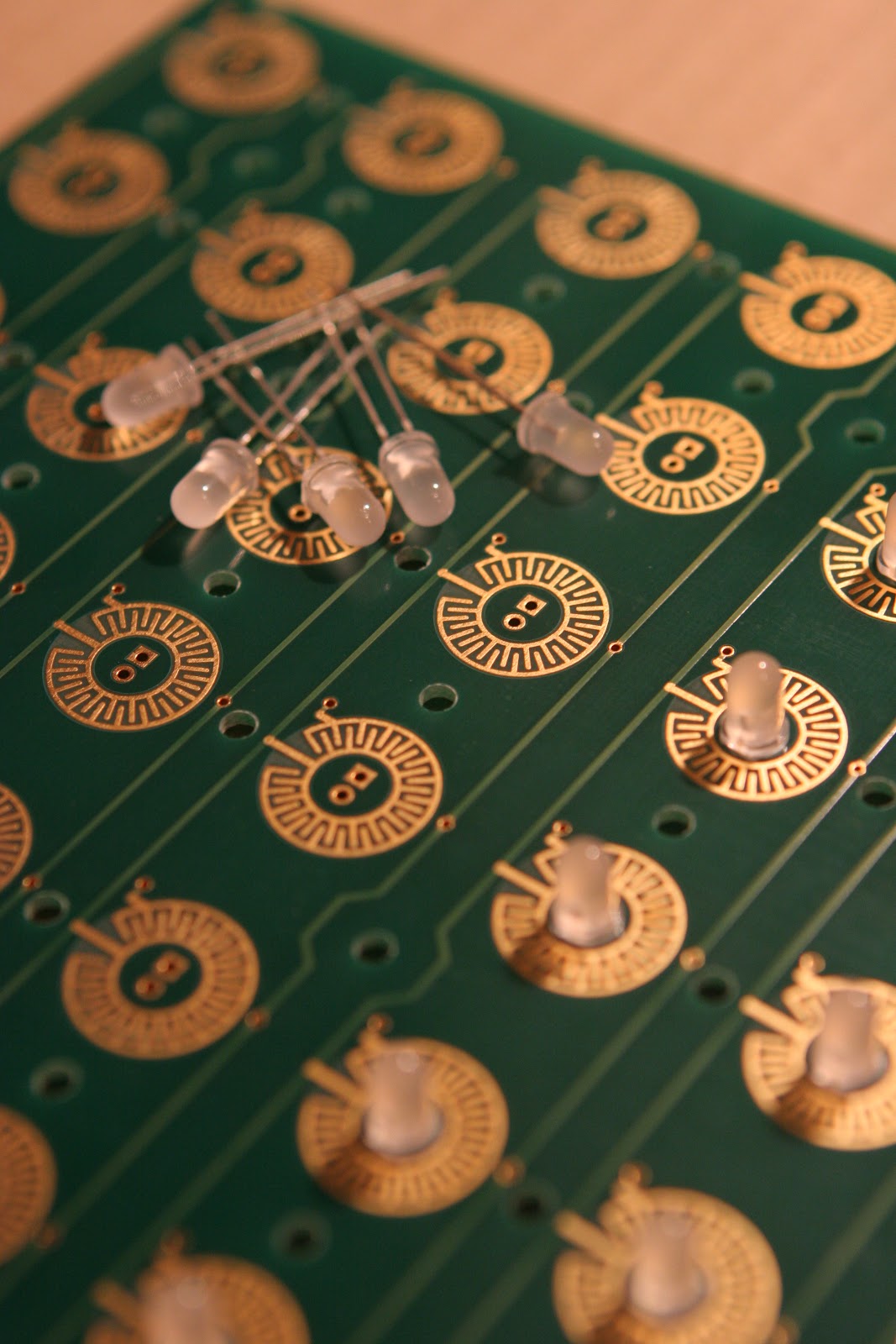
Here is a side project i have, Buliding a monome (or arduinome).
I got the PCBs, MCU, silicon buttons for some time ago but didn't get the time to build it.
Finally i started to solder this stuff.
It is based on a biboboard, sparkfun buttons. for the "intelligence" board, i've got  some unsped board (for Arduinome) or a clone of the 40h monome.

 I don't know yet which one i will use for the monome/arduinome. will try both.

Here  some picture of the ongoing build. I won't comment that much the building process as many blog or website already have extensive documentation on this.

Diodes, diodes diodes ...


Soldering Diodes .. 

Finally all diodes soldered.

Starting to solders Leds .. 


 More and more leds.


Led Closeup 

Ouf .. finished the led soldering ..


Looks good .. :)

Still no big news ...

No this project is not abandonned ..  and  i know that i didn't put many updates on this blog for a while .. so it's time  for a project status :
I've received the new PCB (only few days ago) but didn't get the time to solder it.

I will also put on this blog some side projects or new toys teardown.
So what's next (i hope this week) :
- Solder and test the new PCB (v0.8)
- Finish and test correctly the Speak Spell Library (basic functions)
- Release the Library code.

A quick picture of the new PCB


If you look at the picture, you can see a Midi in and Out, the Speak Spell won't be able to send midi messages. So midi out is not directly used by the speak and spell., but as the project is open source and driven by a Arduino, you will be able to adapt the code to do send midi messages for anything (add midi nutton, sliders,etc..)
The Speak and Spell Shield is also a Midi shield and all connection between Arduino and Speak and spell bus driver can be removed (with the 10x jumpers) so you can disable all the speak and spell electronics and use it as a pure Arduino midi shield for any projects.


vendredi 30 décembre 2011

New Pcb ordered

The new version of the PCB has been ordered (v 0.8)
There is few schematics changes and the Midi connectors has been moved to the back to be able to put this with the Arduino in a case.


And Schematics :


lundi 19 décembre 2011

updates..

Sorry for the lack of update but was busy theses days.

So i've debugged the PCB and it's working fine now .. (need to manufacture another prototype PCB early JAN.)
For the code i'm trying to convert it to a sort of Arduino library, will be much easier to use.


vendredi 18 novembre 2011

It's christmas day

I just received my PCB prototypes they look nice and good quality. :


So quickly let the iron warm up and start to solder 1st prototype.


I soldered only the important parts, because it is the first prototype and you know the murphy's law.
Let's go for the first tests, add S&S power and test some voltage, Guess what .. IT DOESN'T WORK
I got very strange voltage on the output for the speak and spell bus, it's time to start debugging.

After several tests i found why .. all transistors are inverted ..  but strangely i didn't mounted then wrong, the error comes from Eagle. it seems that Eagle got several the BC558 part and one of this part the collector and emitter is inverted and of course i choose the wrong one ..

Next step, remove the transistors and resolder them in the correct way (what a pain to unsolder them on a double side pcb) and re-test. OK now i got the correct voltages. (-18 or 5V). (not with fresh batteries, problem explained in previous post)

midi optocoupler seems to be working right.
Didn't get time to check other part of the pcb for the moment.

Things to change for the next revision :

- correct silkscreen for transistors
- connect transistor emitters to the regulated 5V supply
- correct the input zener input regulation (put resistor in serie)
- check resistors value to limit the schield current
- remove the -18v / gnd selector jumer (default -18V)
- add a jumper to allow power via arduino.